Download this document: /uploads/asset/17b965b06c09.pdf
I. Installing the RFID label and ribbon
1. Place the RFID label into the paper compartment
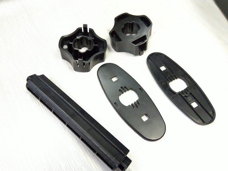
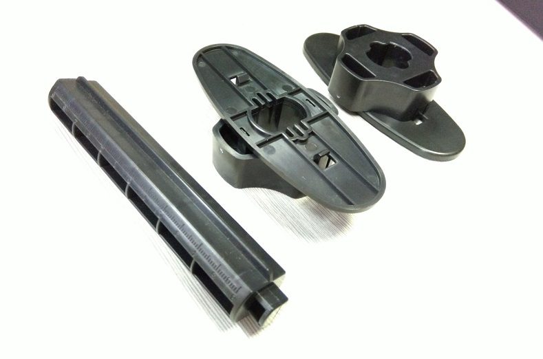
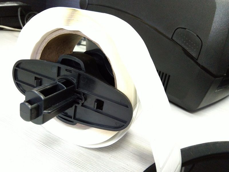
(1) Gather the label installation accessories (2) Clip the paper roll shaft sleeve onto the baffle
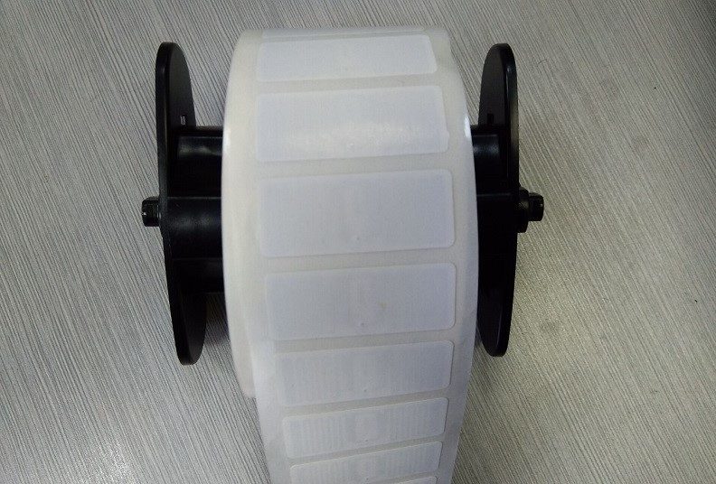
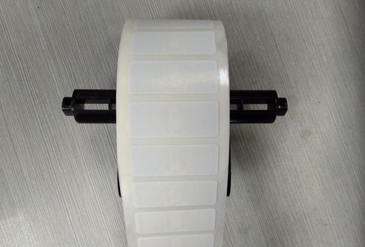
(3) Pass the paper roll shaft through the label core, with the shaft sleeve facing inward (4) Push the baffles in from both sides to center the label; do not clamp it too tightly
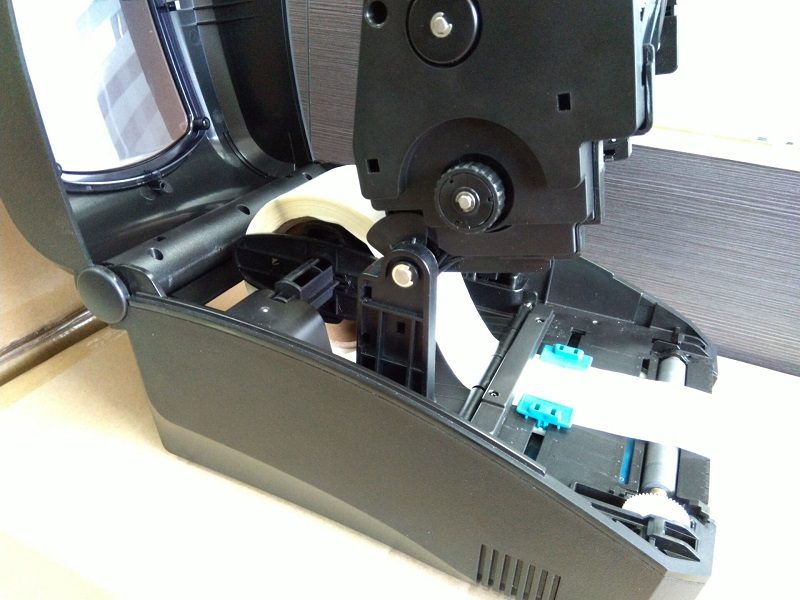
(5) Side view of the paper roll installation (6) Place the installed paper roll into the paper compartment
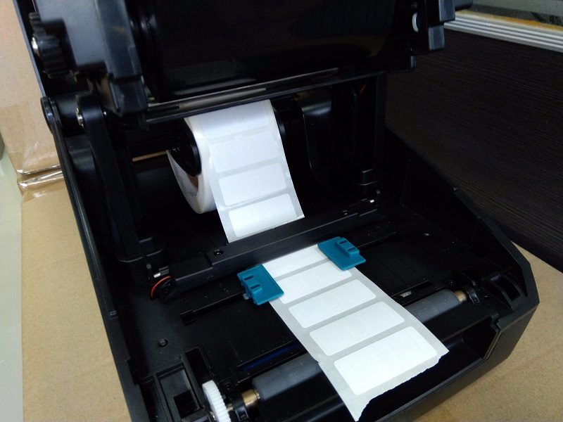
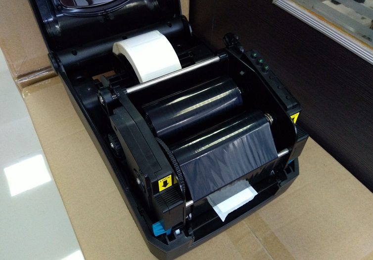
(7) Route the label through the paper guide shaft and secure the blue label guide (8) Close the printhead to complete label installation
2. Using the external paper rack
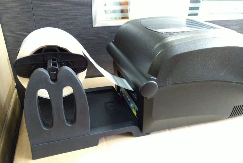
If the paper roll is too large for the printer's paper compartment, use the external paper rack (optional). Installation is shown in the figure above.
II. Connecting the printer to a computer
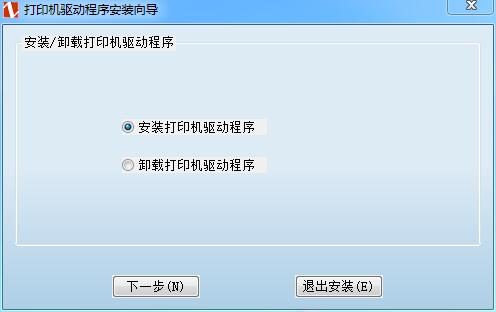
1. Install the printer driver
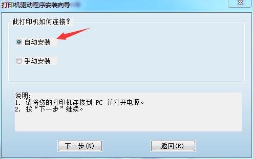
(1) Run the driver installation tool (2) Check automatic installation, then click Next
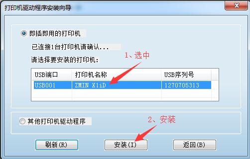
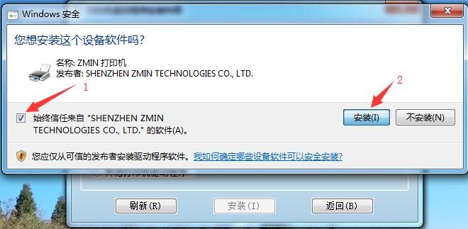
(3) Select the detected printer and click the Install button (4) Check Always trust and click Install
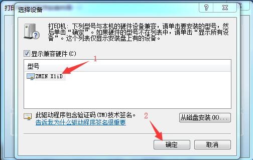
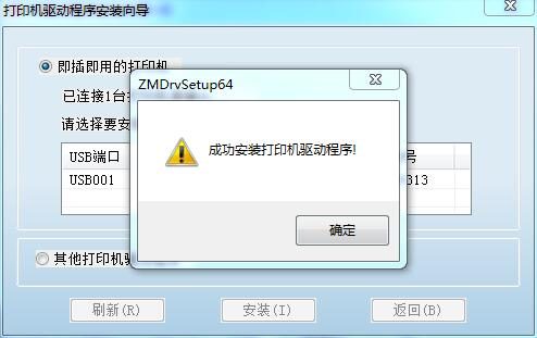
(5) Select the model name and click OK (6) Driver installation is complete
2. Install the LabelSoft label editing software
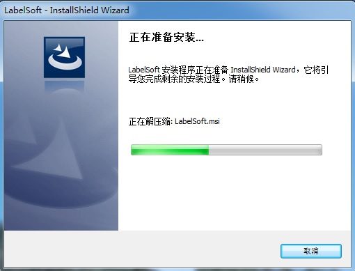
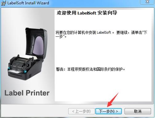
(1) Run the LabelSoft installer (2) Click Next
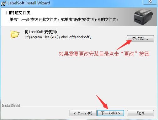
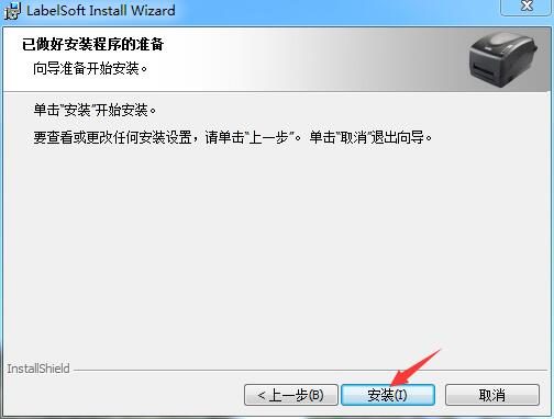
(3) To change the software directory, click the "Change" button (4) Click the "Install" button to start installing LabelSoft
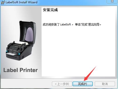
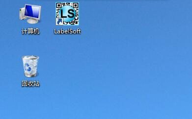
(5) Installation complete (6) A LabelSoft shortcut is automatically created on the desktop
III. Calibrating the RFID label
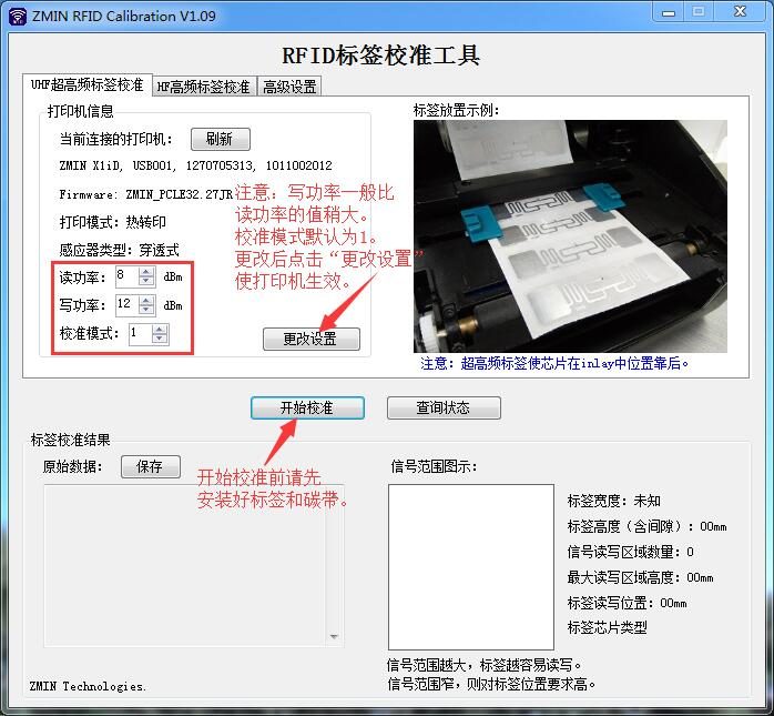
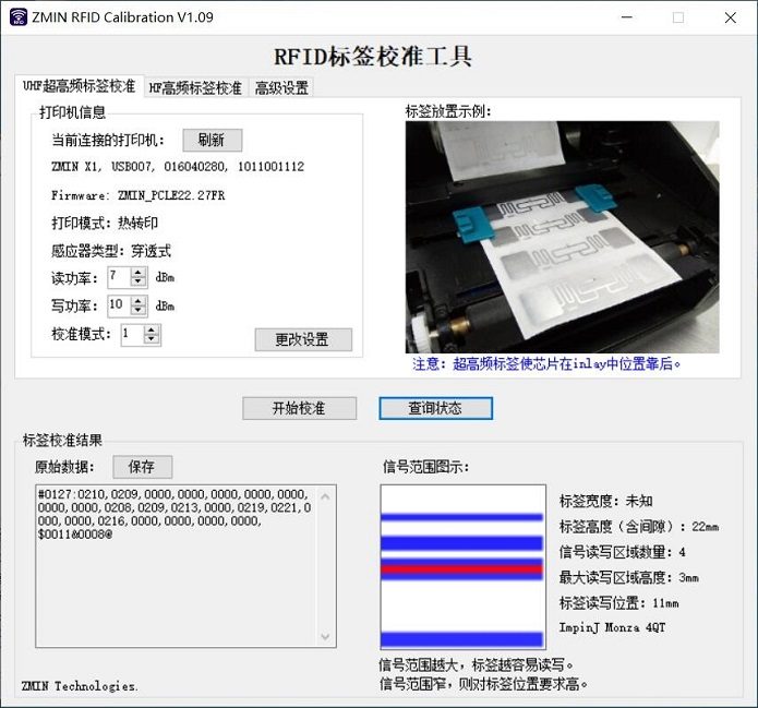
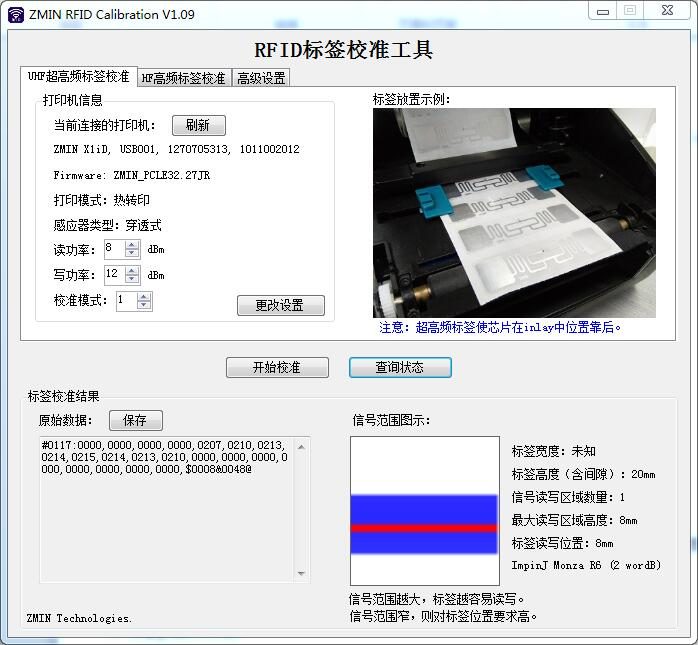
1. Use the visual label calibration tool
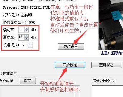
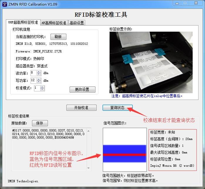
Set the read/write power to control the RFID module and obtain an ideal signal range.
The signal distribution shown in the left figure is relatively ideal.
2. Printer DIP switch description
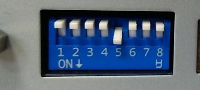
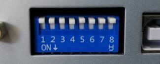
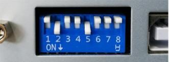
| DIP switch settings: 1. Down: ribbon sensor off, thermal mode; Up: ribbon sensor enabled, thermal transfer mode. 2. Down: RFID module off, print ordinary labels; Up: RFID module enabled, print RFID labels. 3. Cutter: keep the switch up. 4. Peeler: keep the switch up. 5. Down: use the transmissive sensor; Up: use the reflective sensor. 6. Network setting function: keep the switch up. 7. Used together with 8 to set the serial port baud rate; please consult technical personnel for details. Note: After changing DIP switches, the printer must be powered off and on again. | DIP switch settings: 1. Down: ribbon sensor off, thermal mode; Up: ribbon sensor enabled, thermal transfer mode. 2. Down: RFID module off, print ordinary labels; Up: RFID module enabled, print RFID labels. 3. Cutter: keep the switch up. 4. Peeler: keep the switch up. 5. Down: use the transmissive sensor; Up: use the reflective sensor. 6. Network setting function: keep the switch up. 7. Used together with 8 to set the serial port baud rate; please consult technical personnel for details. Note: After changing DIP switches, the printer must be powered off and on again. |
DIP switch settings: 1. Down: ribbon sensor off, thermal mode; Up: ribbon sensor enabled, thermal transfer mode. 2. Down: RFID module off, print ordinary labels; Up: RFID module enabled, print RFID labels. 3. Cutter: keep the switch up. 4. Peeler: keep the switch up. 5. Down: use the transmissive sensor; Up: use the reflective sensor. 6. Network setting function: keep the switch up. 7. Used together with 8 to set the serial port baud rate; please consult technical personnel for details. Note: After changing DIP switches, the printer must be powered off and on again.
DIP switch settings:
1. Down: ribbon sensor off, thermal mode; Up: ribbon sensor enabled, thermal transfer mode.
2. Down: RFID module off, print ordinary labels; Up: RFID module enabled, print RFID labels.
3. Cutter: keep the switch up.
4. Peeler: keep the switch up.
5. Down: use the transmissive sensor; Up: use the reflective sensor.
6. Network setting function: keep the switch up.
7. Used together with 8 to set the serial port baud rate; please consult technical personnel for details.
Note:
After changing DIP switches, the printer must be powered off and on again.
(1) Printing RFID labels with the transmissive sensor
(2) Printing RFID labels with the reflective sensor
(3) Printing ordinary non-RFID labels with the transmissive sensor
IV. Layout, editing, and printing
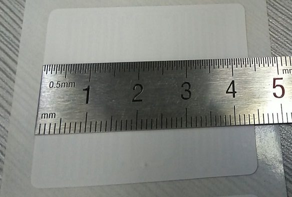
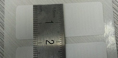
1. Measure the label size
(1) The label width measured with a ruler is 44mm (2) The height is 18mm
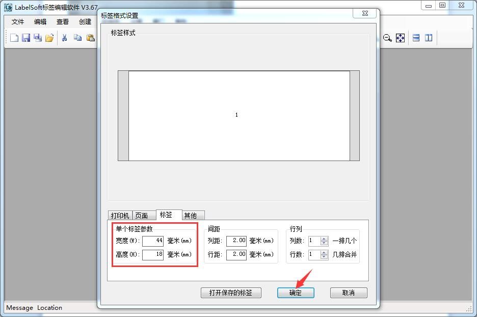
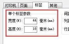
2. Set the label size in LabelSoft
3. Add the text, barcodes, RFID objects, etc. to be printed
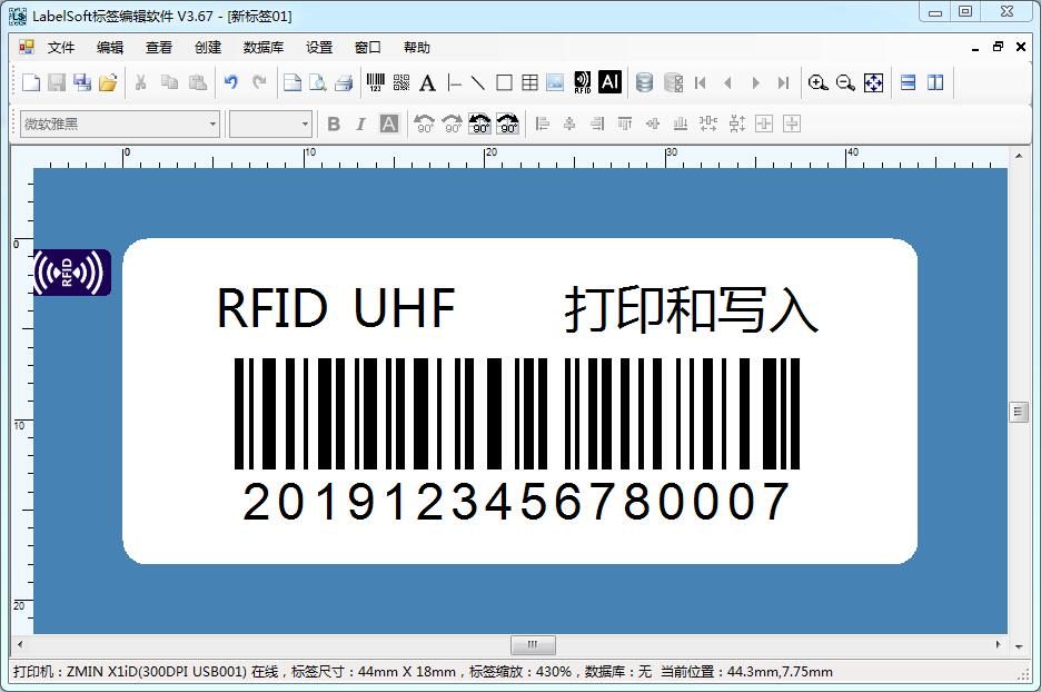
(1) Print and write EPC data
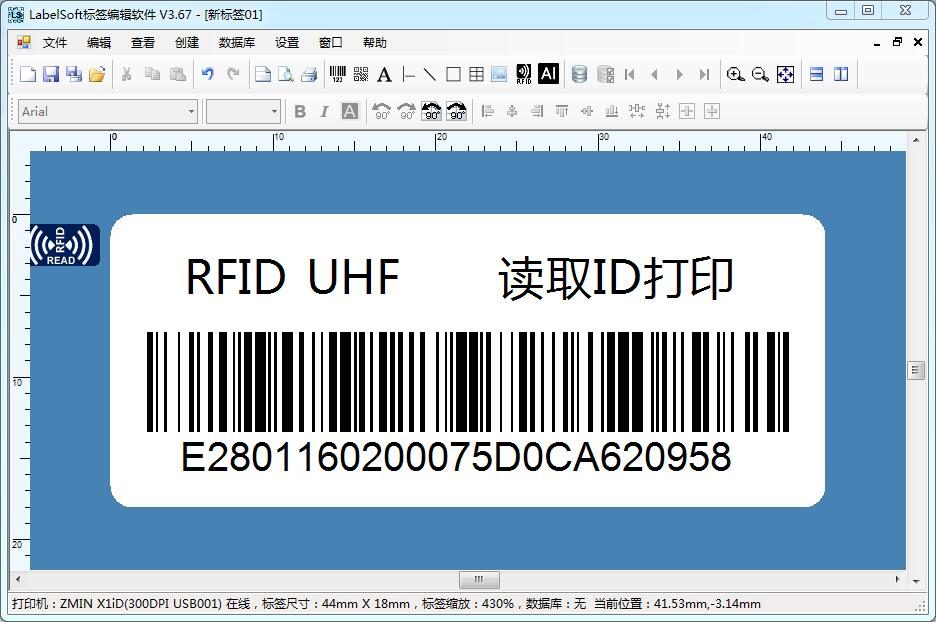
(2) Read the label ID and print it as a barcode
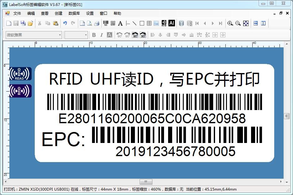
(3) Read the ID, write the EPC, and print
V. Troubleshooting
1. Incorrect calibration signal
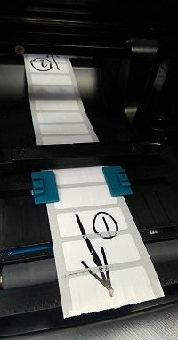
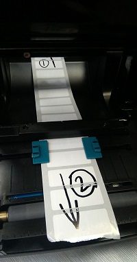
(1) Signal dispersion is not ideal, prone to read/write errors (2) Concentrated signal with a large write area is the ideal signal distribution
If the situation shown in figure (1) occurs, try turning the label around and calibrating again.
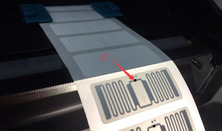
RFID labels have a certain directionality. Generally, the chip is located at the rear part of the label, where the signal is relatively stable, which helps stable reading and writing.
2. Frequent errors during printing
The label calibration is normal and the signal distribution is concentrated, but printing and reading/writing often fail.
In this case, first check whether label consistency is normal: perform RFID calibration 3-5 times and see whether the signal distribution after each calibration is similar. If the signal distribution differs greatly each time, the label consistency may be poor; try other labels.
If the signal calibration is basically consistent each time, the read/write failure may be caused by label slipping. Check whether label feeding is smooth. Especially when using the external paper rack, the label should not be clamped too tightly, and the feed path should have no bends or other obstructions. In addition, lowering the print speed increases motor torque; the default is generally 4 inches/sec, and at 6 inches/sec some labels may jam or slip.
3. Calibration is normal but printing fails
The label calibration is normal and the signal distribution is concentrated, but printing and reading/writing fail immediately, without a single success.
This is very likely due to an incorrect data write format. RFID label EPCs have capacity and write-bit limits; for example, a 96-bit EPC capacity allows writing at most 12 bytes of data, and exceeding it causes write errors. Most chips require the minimum write unit to be a byte, while some chips require the minimum write unit to be a double word (4 bytes). Consult the label supplier about the chip's capacity and write format restrictions, and write data in the correct format.
4. Abnormal HF calibration
If HF labels fail calibration repeatedly, confirm whether the label protocol type matches the setting in the software; calibration cannot succeed if the protocol type is inconsistent. HF (13.56MHz) supports 15693, 14443A, and NFC/UltraLight protocols. Use the RFID calibration tool to set the printer's current working protocol type, and after setting the correct protocol, perform RFID label signal calibration.
The above are the standard steps for using ZMIN RFID printers. If the above information does not solve your problem, please contact us for technical support as follows:
Weekdays 9:30 to 17:30
QQ: 2307385981
Telephone: 0755-23213336
At other times, please visit our website for more technical support information or send an email to: support@zmin.com.cn
Shenzhen ZMIN Technologies Co., Ltd.
/